Iron foundry basics
Practical Action
drag) is placed around it, making sure the jointing side is to the board. The board should be of
sufficient area to cover the full face of the moulding box being used, and have battens fixed to the
underside which must be deep enough to give clearance for the locating pins which are part of the
moulding box (drag). Moulding sand is added, until the box is almost full. The sand must be
rammed hard, so that it forms a solid mass around the edges of the moulding box and pattern, and
completely fills the box with sand by ramming hard with a flat rammer. Any excess sand which
projects above the upper edge of the moulding box is then scraped level (Fig. 13).
Figure 11: Alternative method of box selection
The half mould is turned completely
over exposing the half pattern which
is left fixed to the mould. The
second half of the pattern is placed
on the half that is already in the
mould, being located and aligned
by means of the dowel pins in the
pattern. The top half (the cope) of
the moulding box is positioned to
the bottom half and aligned by the
lugs and corresponding holes.
Parting powder, a dry fine refractory
powder (preferably alumina) is then
dusted over the joint fact, to
prevent the two faces from
adhering. Moulding sand is now
added to this half of the moulding
box, using the same method that
has been previously explained (Fig.
14).
The moulding box is now split and
two halves are placed on the board
side by side, exposing the patterns.
The two half patterns are removed
from the moulds. This is done by
driving or screwing a small metal
rod into the patterns and gently
tapping the patterns in a horizontal
plane until they are loosened, so
that they can be carefully drawn
out. Care must be taken so that the moulds are not damaged during this operation.
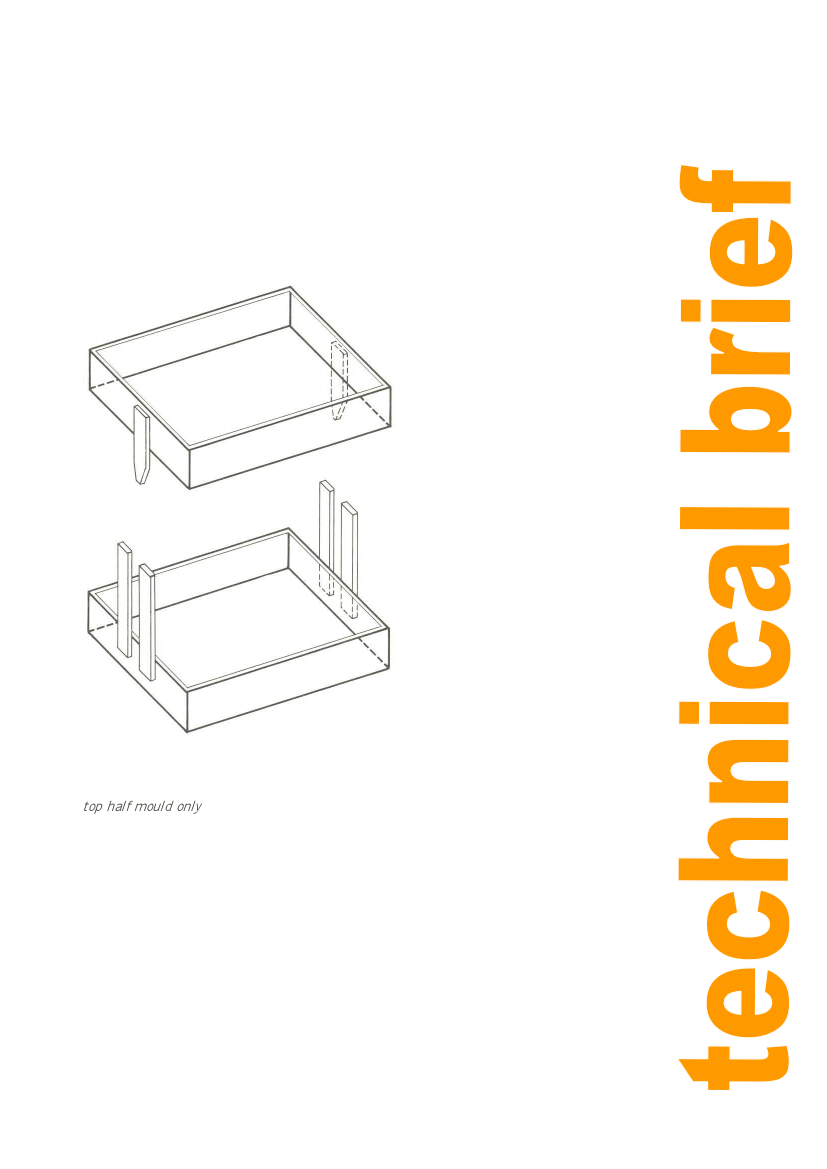
Channels or runners are cut into the horizontal exposed faces of one or both of the moulds and in
the top half mould only a vertical channel is cut, connecting from the horizontal channel to the
upper surface of the mould. This is to allow the molten metal to be poured into the impressions left
in the sand. Normally a thin walled tube of the correct diameter, with a sharp edge at one end, is
used for the purpose of making the vertical channel, as it can be pushed straight through the
mould. Any core or cores are
now carefully placed in the required positions.
The top half mould can now be replaced onto the bottom and the two boxes are clamped together.
The mould is now ready to receive molten metal (Fig. 8).
Sands
Various sands are available for the making of moulds and cores. The nature of the sands is
important, as they can affect the type and quality of castings produced. Information on sands that
are available locally, and their suitability for foundry work should be sought from a University, in
the area where it is intended to. set up the industry. I.T.D.G. can also provide additional general
information on the subject. The following definitions of some foundry terms are included for the
benefit of readers who are not familiar with their precise meaning.
11